Eye in the dark
2025-11-14 | By Mustahsin Zarif
License: Attribution Breadboards Voltage Arduino
Transistors and light-dependent resistors (LDRs) have been used in combination to build plenty of useful devices around us. For example, street night lights operate on the principle that they have to turn on when it gets dark outside. I wanted to exploit the circuit behind this by switching the LED out for a round LCD to show Big Brother’s eye from George Orwell’s book “1984.” Then, I could plant this in someone’s room, and the moment they turn off their lights to go to bed, they see an eye staring at them.
Here is a diagram of the circuit to be made, created using DigiKey’s Scheme-it:
The operation is simple yet very interesting and practical.
In the middle, we have an NPN BJT in series with a load at the collector. When the BJT is on, current flows through the screen, and it turns on.
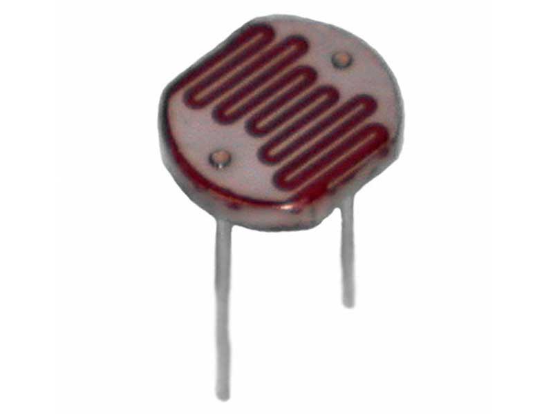
On the left, we have a potentiometer followed by wires branching to a photoresistor and the base of the BJT. The potentiometer is used so that we can adjust the resistance to set up a threshold depending on where we want to set up. The photoresistor has low resistance in the day, so most of the current flows through it instead of the base of the BJT. In the dark, the photoresistor resistance increases, so more current flows into the base of the BJT, and it turns on.
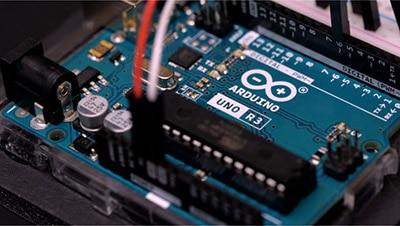
On the right, we have the Arduino supplying the 3.3V logic needed to operate the LCD screen. It also sends display information to the LCD screen over SPI. The ground of the circuit is also set by the Arduino. Note that this is a significant difference from street night lights, which do not need programming data and operate using a battery/external power supply instead of an Arduino.
Great. Now that we have the schematic, we can buy the parts needed from DigiKey:
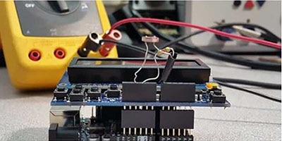
With the parts, we can set up the circuit on a breadboard and program the Arduino using the code in my GitHub repository.
Display SPI connections:
VCC --> 5V
GND --> Collector pin of 2N222A
SDA --> D11
SCL --> D13
CS --> D10
DC --> D7
RST --> D8
BJT connections:
Collector --> GND of display
Emitter --> GND of Arduino
Base --> one leg of photoresistor, middle pin of potentiometer (check schematic)
The code looks complex, since the process to set up a display is always tedious, but I have a function "drawIntimidatingBigBrotherEye();" that takes care of drawing everything needed for an eye (sclera, pupil, iris, additional details) using common shapes such as circles and ellipses. I also use helper functions such as the "void drawEllipseOutline(int16_t x0, int16_t y0, int16_t rx, int16_t ry, uint16_t color)" to draw ellipses around a center point.
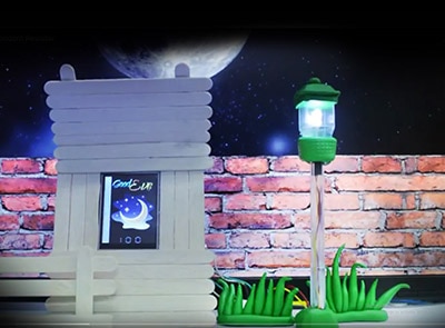
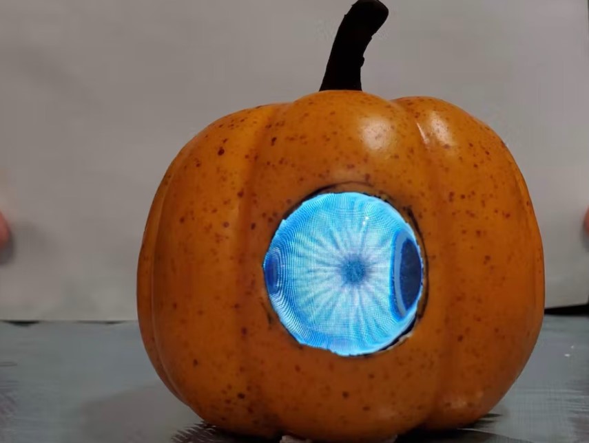
Finally, after adjusting the potentiometer, we can see the results:
In bright light: screen off
In the dark: screen on
Bonus: video of me trying to take a picture of the display in the dark without turning off my flash: https://youtube.com/shorts/osZLgOP47YM?si=bDL9VvnSgvdoajUg
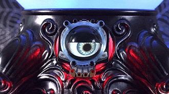
You can change the Arduino code to show anything else you would like, for example, if you want to make a dragon eye like I did. You can also do more fancy animations, but try switching to an ESP32 since the Arduino Uno R3 does not have enough memory to handle large requests. Also, even though I wanted to play around with analog circuits, you would be better off using the analog pins on the Arduino to read the photoresistor value and define a proper solid threshold to turn on the display instead of adding all the circuitry. Nevertheless, this is still a great way to understand how streetlights work!